An elective offered at CU Boulder is Mechatronics and Robotics I. This course introduces microprocessor architecture and programming, sensor and actuator selection, robotic systems, and design strategies for complex multi-system devices.
For a semester-long group project with a class-driven theme, we organized a class competition. Our objective was to design an autonomous, tank-like robot capable of navigating a maze-like arena while competing in a game of dodgeball
The final design report can be downloaded below, and my contributions are documented throughout this page.
Rules
A set of constraints and rules was established by our professor to guide the design process.
Key rules included:
Budget: Total project cost must not exceed $200.
Size: The robot must fit within a 14” x 14” box and not exceed 15” in height, including the unobstructed height of the can.
Target Identification: The robot must carry a coffee can wrapped in a 'hot' pink sweatband for target identification by the opposing robot. The can must be mounted at the top, with its bottom positioned 10" from the floor, the top 15" from the floor, and with a tolerance of 0.25". The lower three-fourths of the can may be obscured or used for stabilization, but the upper 5" must remain unobstructed.
Projectiles: Only approved projectiles are allowed, with Nerf Rival balls chosen for our design.
Autonomy: The robot must operate autonomously and will be placed randomly at the start of each round within the designated starting areas.
Components: The robot may have a maximum of three microcontrollers or similar devices and can carry up to two cameras (IR sensor pairs are excluded).
Preliminary Design
Our initial design was inspired by the movement principles of the popular iRobot Roomba. The drive system enables the robot to rotate and turn in place by moving the wheels in opposite directions, allowing it to pivot left or right on the spot.
Initial Design Diagram
For autonomous navigation and detection, we used two IR sensors and a Pixy camera for object detection. The IR sensors were mounted at the front of the chassis, facing downward to track the floor color. If the sensor detected white, indicating the robot had reached the white tape marking the battlefield boundary, it would register the boundary and turn to avoid crossing it. If the sensor detected black, meaning the robot was within bounds, it would continue normal operations, including navigating the battlefield and locating opponents. A front-facing sonar sensor worked in tandem with the IR sensors to prevent collisions with obstacles.
Above the main chassis, multiple levels of laser-cut acrylic supported the electronics, firing mechanism, Pixy camera, and coffee can target. These levels allowed for better organization and isolation of electronic components, improving system packaging. They were easily adjustable using wingnuts to accommodate the necessary electronics.
Chassis Design
The robot's chassis was 3D-printed using a design created in SolidWorks, providing mounting locations for all electrical and mechanical components. The chassis was made from PLA, allowing for rapid design iterations with fewer restrictions. The main base accommodates the wheels, stepper motors, and mounting spots for IR sensors and radar. These mounting locations were integrated into the 3D-printed design to ensure compact packaging of the drive mechanism.
3D-Printed Chassis with Motors, Wheels, and Bearings Installed
Motion from the drive wheels works in tandem with the sonar and IR sensors to detect boundary lines or physical obstructions. When an obstacle or boundary is detected, the robot rotates in place until the path is clear. This allows the robot to navigate the arena in a waffle pattern until a competitor is detected, triggering the firing mechanism.
CAD Model of the Base Chassis
The robot’s movement is powered by two wheels connected to stepper motors, while two spherical bearings provide additional stability for the chassis.
Corner View of 3D Printed Chassis with Wheels
Motion from the drive wheels works in tandem with the sonar and IR sensors to detect boundary lines or physical obstructions. When an obstacle or boundary is detected, the robot rotates in place until the path is clear. This allows the robot to navigate the arena in a waffle pattern until a competitor is detected, triggering the firing mechanism.
Complete Shooter Assembly with Nerf Balls Loaded In
Interior of Barrel with a View of the Magazine
The Pixy Camera was optimized to see the hot pink sweatband that was placed on top of every team's robot. Ours specifically was placed right on top of the shooting mechanism to allow for precise object recognition and tracking. This positioning enables the camera to quickly shoot directly at what it's looking for rather than having to adjust and lose time.
Front View of the Physical Shooting Mechanism
PixyCam Used for Computer Vision
Shooting Mechanism
Side View of the Physical Shooting Mechanism
The flywheels are powered by two DC motors to propel the balls forward. Made from TPU 3D printer filament, the flywheels offer flexibility to grip the balls as they pass through the firing mechanism. The flywheels, motors, and internal projectile track are housed within a 3D-printed chassis positioned on the top level of the robot. The firing mechanism works with the Pixy cam to detect when the robot is facing the opposing target. After a set interval, the solenoid releases a ball to be fired.
To conserve battery due to the motors' high current draw, the firing motors do not run continuously but only activate when a target is detected.
Complete Firing Mechanism Assembly
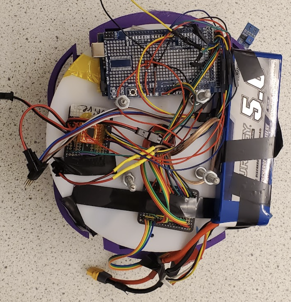
The robot is controlled by an Arduino Mega and an Arduino Uno, which communicate via an input pin on the Uno and an output pin on the Mega. The Arduino Mega manages the robot’s physical movement and pathfinding, sending signals to a motor controller that operates the two main drive motors. It also receives telemetry from the two infrared sensors, the sonar sensor, and the PixyCam. The Mega is connected to a shield circuit board, which has dedicated connections to separate daughter boards for the motor controller and sensor suite.
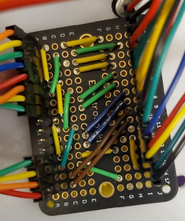
Sensor Breakout Daughter Board
The Arduino Uno, in contrast, controls the ball interaction mechanism. It sends signals to a daughter board that houses a motor controller, which operates the flywheel motors on one side and the release solenoid on the other.
Lower Layer: Arduino MEGA, Lipo Battery, Wheel Motor, Driver, and Electronic Cookie for Sensors Suite.
Circuit Design
Motor Controller Daughter Board
Upper Layer: Shooting Motor Driver, Arduino UNO, and Power Switches for Flywheels.
Arduino Mega Shield with Soldered Connections
The Arduino Uno, in contrast, controls the ball interaction mechanism. It sends signals to a daughter board that houses a motor controller, which operates the flywheel motors on one side and the release solenoid on the other.
7.4V and 11.1V Power Rocker Switches
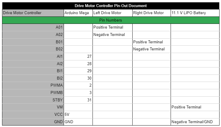
The 11.1V battery powered the Arduino Mega via a barrel jack and supplied the drive motors through a connection with the Vm pin. The Mega then distributed 5V to the sensor suite and motor controller from its onboard 5V terminal.
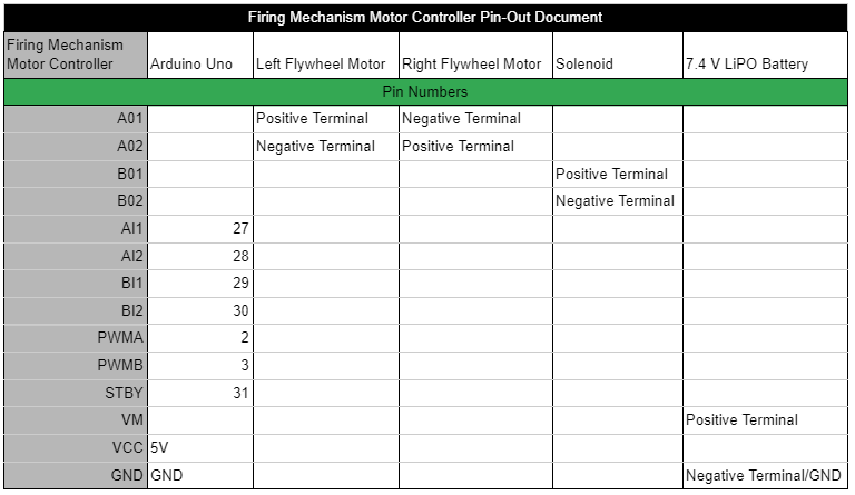
The 7.4V battery powered the Arduino Uno via a barrel jack and supplied the flywheel motors through the Vm pin. The Uno then provided 5V to the motor controller from its onboard 5V terminal.
Daughter boards became necessary after encountering multiple shorts and open connections in the full-function shield. They allowed for easier troubleshooting, both during assembly and testing of individual mechanisms. Additionally, they facilitated quick replacement of damaged components.
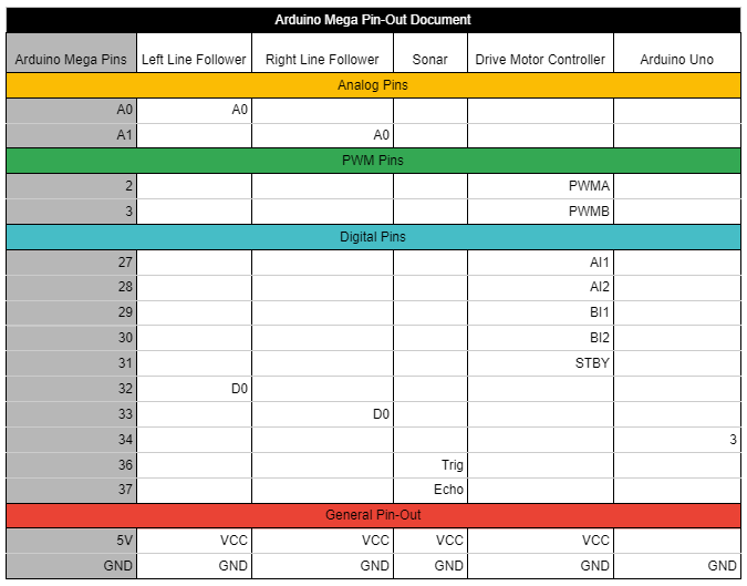
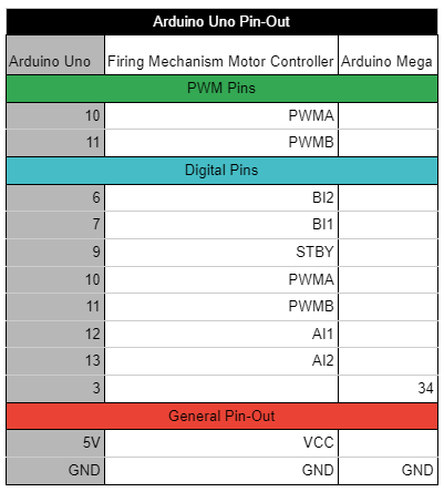
The following tables show the pin-to-pin connections for all electrical components within the robot. The first table details the connections for the Arduino Mega, the second for the Arduino Uno, the third for the Drive Motor Controller, and the final table outlines the pin-out for the Firing Mechanism Motor Controller.
Coding/Functionality
The shooting mechanism operates by keeping the flywheels running at a low RPM while the Uno board continuously monitors for digital input from the Mega. When a high state is detected on the input pin, the flywheels spin up to a higher RPM, and the solenoid is triggered to release a Nerf ball. After firing, the flywheels slow down again. This process runs independently of the Mega, allowing the robot to continue tracking the opposing robot during spin-up and firing.
The video above shows our robot starting in a corner and navigating the arena while avoiding the lines and boxes
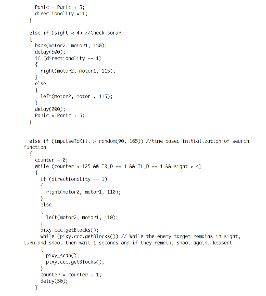
If no enemy robots are detected in their starting position, the Mega uses the two front IR sensors and the front-facing sonar sensor to determine which sides are clear for movement. Based on this input, the robot moves left, right, or backward at an angle to avoid obstacles.
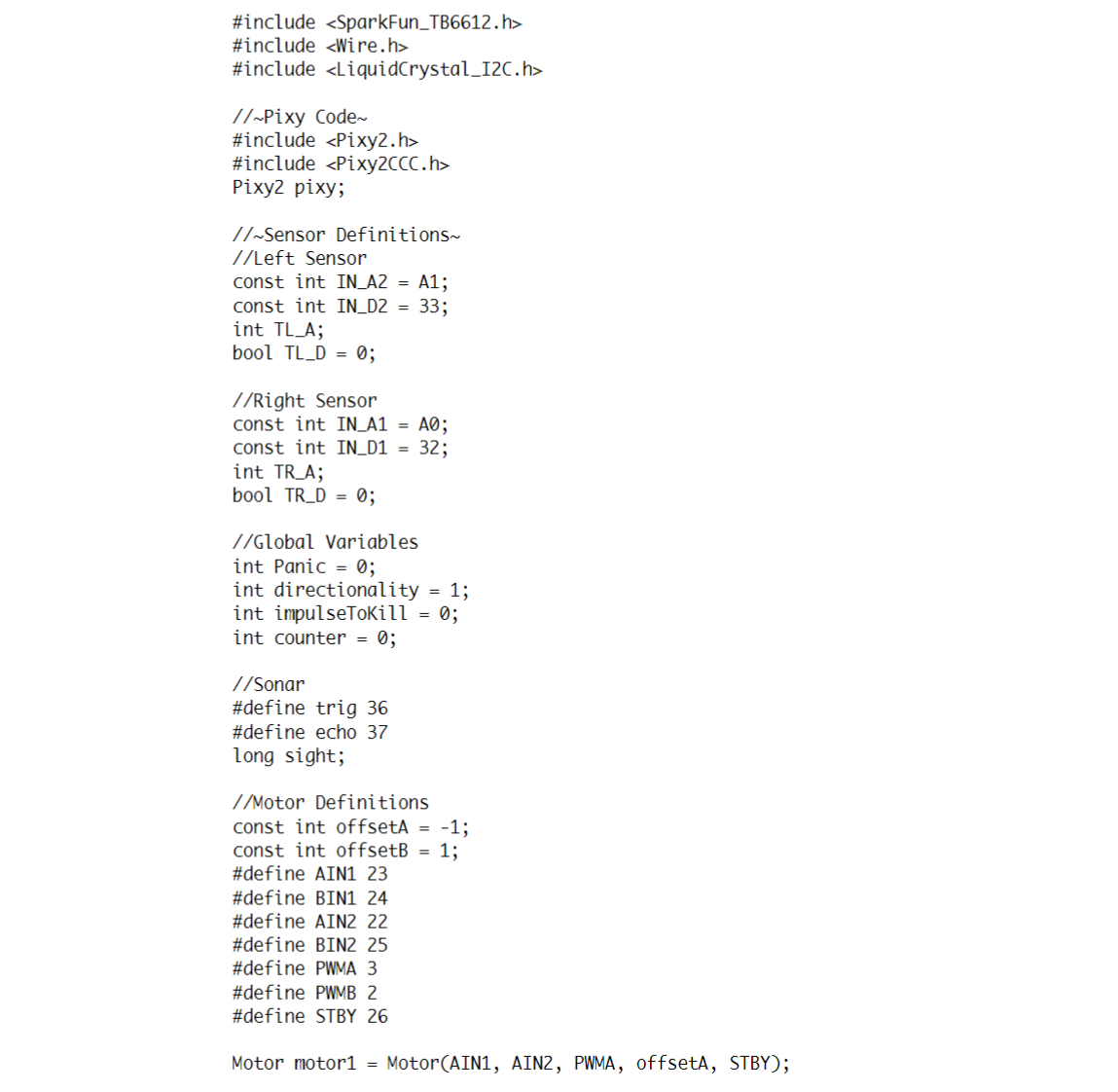
A variable called 'directionality' was implemented to address edge cases: if the robot starts moving right to escape a corner, it is more likely to continue turning right if multiple sensors are activated simultaneously. Another variable, 'panic,' was added to handle situations where the robot becomes stuck in a corner. This variable counts down to 0 when moving straight but counts up to 70 when avoiding obstacles, at which point the robot makes a full turn. If no sensors are triggered, the code proceeds to the next step in the decision matrix.
When no enemy robots or obstacles are detected, a generic movement code is executed. The robot drives forward in a straight line to avoid incoming shots and potentially reach a vantage point to gain line of sight with an enemy robot, initiating the firing process. After moving forward for a set duration without interruption, the robot performs a 360-degree pivot, using the PixyCam to search for targets as described earlier. This is the final stage of the control system before it loops back to the beginning.
The video above shows our robot scanning for potential targets before continuing to navigate the maze
The robot's control system for this project uses two interconnected Arduinos, linked via ground pins and a shared digital input/output pin, as outlined in the previous section. The main Arduino Mega serves as the primary control system, running code that uses a decision matrix based on sensor inputs and internal variables to control the robot’s movement in the arena. The secondary control system, an Arduino Uno, is dedicated solely to managing the firing mechanism.
The robot's initial action, regardless of its starting orientation, is always to scan with the Pixy 2 camera to determine if it’s facing the opposing robot. This ensures that it prioritizes scoring by attempting to shoot other robots rather than evading shots from other teams. This strategy proved effective during the first round of the tournament, as the robot remained stationary when it detected the opposing robot and attempted to unload all available ammunition.
The video above shows our robot detecting the pink sweatband on top of an opposing robot, centering its aim, and then firing
If the Pixy cam detects an enemy, one of two scenarios can occur. In the first scenario, the enemy is detected but not centered in the Pixy cam’s view. The robot will then turn to align the enemy in the center, triggering the second scenario. In this scenario, when the enemy is centered in the Pixy cam’s view, the robot immediately initiates the firing process.
This process begins by setting the Mega’s digital output pin to high, signaling the Uno to start shooting (detailed in the next paragraph). After firing, the tracking process resumes. If the enemy remains centered, the robot fires again. If the enemy is detected but off-center, the first scenario is repeated. If the enemy leaves the Pixy cam’s sight line, the robot reverts to the movement matrix.
The Arduino code controlling all the actions described above is listed in the slide deck to the left.


