At CU Boulder, the Component Design course builds on concepts from Solid Mechanics and Statics, taking a more applied approach. In this class, students design and manufacture a bike powered by a 20V DEWALT drill.
The project encourages students to challenge themselves under real-world engineering standards, with constraints such as a set timeline, a budget of less than $200, and a maximum bike weight of 50 lbs.
The final design report can be downloaded below, and my contributions are documented throughout this page.
Race Course
There were three races that students could choose to participate in and optimize their design to the requirements of one. These included a hill climb, maneuverability, and the endurance race.
For us, the endurance race was the main event we chose to compete in. The race course spans about 1,100 feet over uneven grounds with various slopes and hills. The challenge was to complete as many laps as possible within a 30-minute time limit. The moment the vehicle comes to a complete stop or the driver touches the ground is when a team’s attempt is over. The battery for the drill used to propel the bike forward would also not be able to be replaced during the race.
Figure 1: Endurance Race Course
Design Process
With this in mind, our proposed design focused on being lightweight to extend the drill’s battery life for the 30-minute time limit while also improving the rider’s agility during turns.
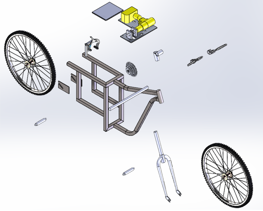
We considered two initial concepts: a tricycle and a scooter-based design. The tricycle concept, shown in Figure (2), offered a simpler frame design compared to the scooter.
The tricycle’s advantage is its stability, making it easier to climb slopes. However, it sacrifices agility, especially when maintaining high speeds on downhill turns. Additionally, the tricycle could be heavier due to the extra wheel, potentially increasing the battery consumption throughout the race.
Figure 2: Initial Tricycle Design
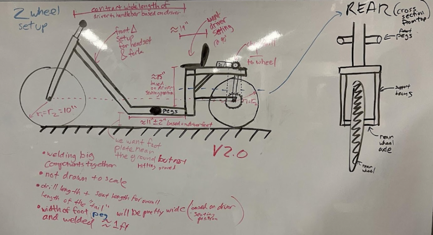
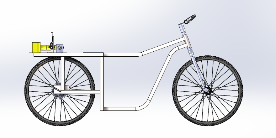
While the tricycle frame was relatively easy to manufacture, the two-wheel scooter’s geometric design offered significant advantages for racing. Its lightweight structure not only improved acceleration but also made it more maneuverable, enhancing performance during turns and overall agility. Additionally, the scooter provided better space for drivetrain layout. For example, as shown in Figure (3), the chain tension in the drivetrain was oriented vertically behind the rider, further optimizing weight distribution.
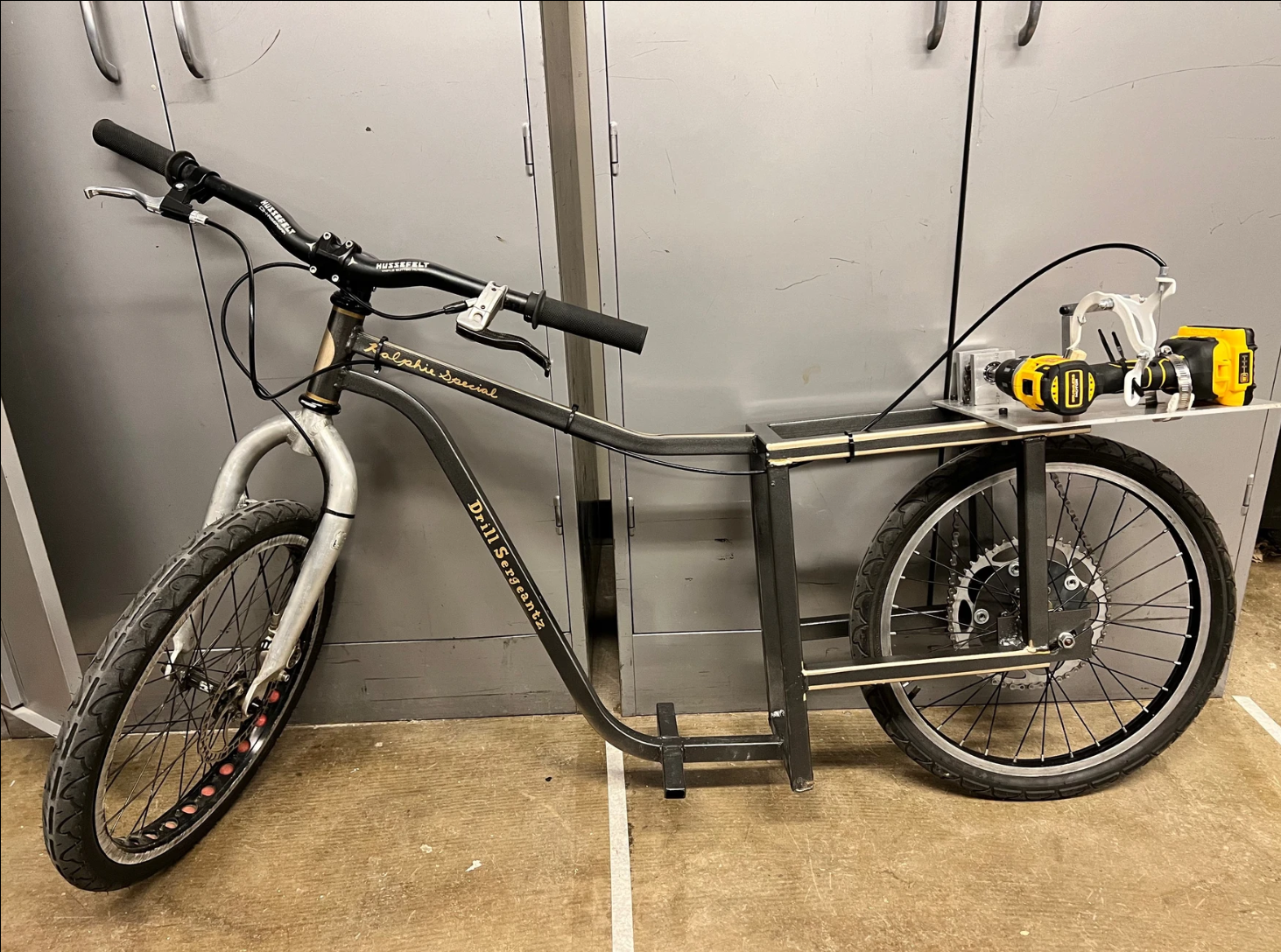
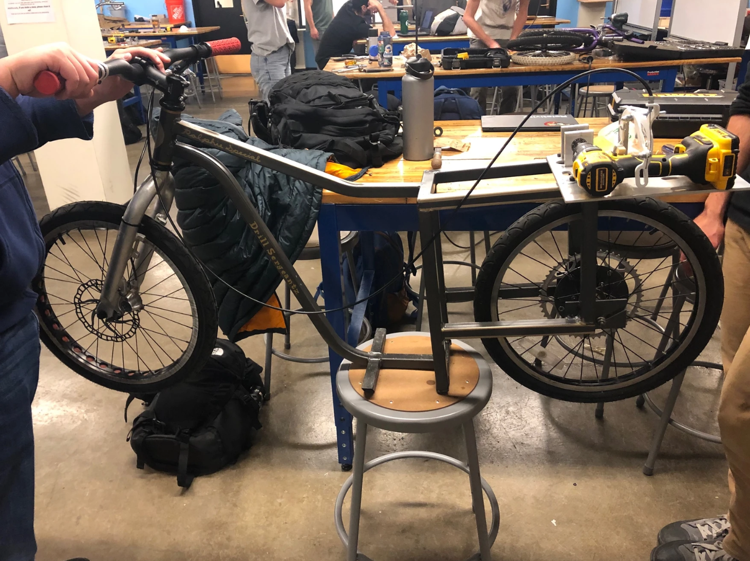
The scooter design featured a compact, lightweight frame that could withstand the load of the driver and components. We built the frame around 20” wheels, which allowed for quicker acceleration and reduced the load on the drill compared to larger wheels. The drill was mounted behind the rider on a drill plate, maximizing space for the rider’s feet. The drill’s shaft drove a rear sprocket connected to the rear wheel, which had a 48T chainring attached to a freewheel, allowing the driver to turn off the drill when needed.
For the front end, we used standard bike components like a headset, fork, and handlebars, allowing for easy customization and installation.
Figure 3: Initial Scooter Design
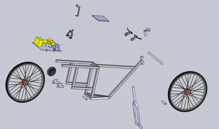
An initial vehicle assembly was created in SolidWorks to showcase our envisioned scooter-based design. After a design review, we made adjustments to reduce weight and improve manufacturability. The initial design is shown on the left.
We made several design changes to enhance the scooter’s performance and manufacturability:
Removed two redundant angled beams from the footrest.
Altered the top and down tubes with angled points, creating two contact points with the head tube, reducing the number of cuts and welds.
Simplified the dropout design for easier manufacturing without compromising effectiveness.
Removed the derailleur and cassette, as they could have been too harsh on the drill.
The updated design is shown on the right
Once we had designed each of the bike components and made it into an assembly, drawings were created for manufacturing. I was involved in helping create every engineering drawing for our bike components. All of the finalized drawings we used are shown in the slide deck.
Components requiring machining were distributed among group members. I was primarily responsible for:
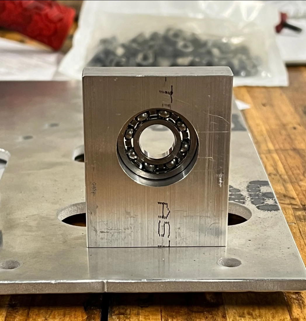
Pillow Blocks (x2) using a knee mill – These components transmit the drill’s torque to the chain, enabling the bike's movement.
Drive Sprocket using a lathe – This component works with the chain and drive shaft to propel the bike.
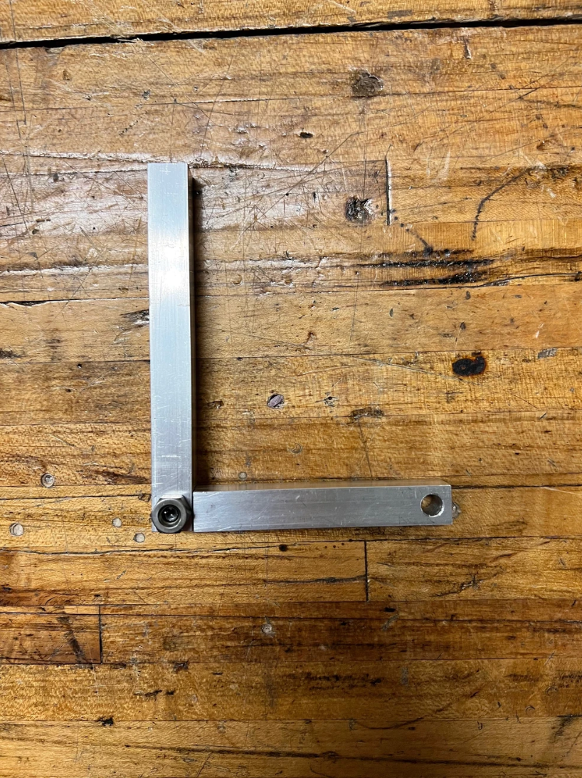
Throttle Mount using a knee mill – This component clamps onto the drill’s trigger, allowing the rider to use the handlebar throttle for acceleration.
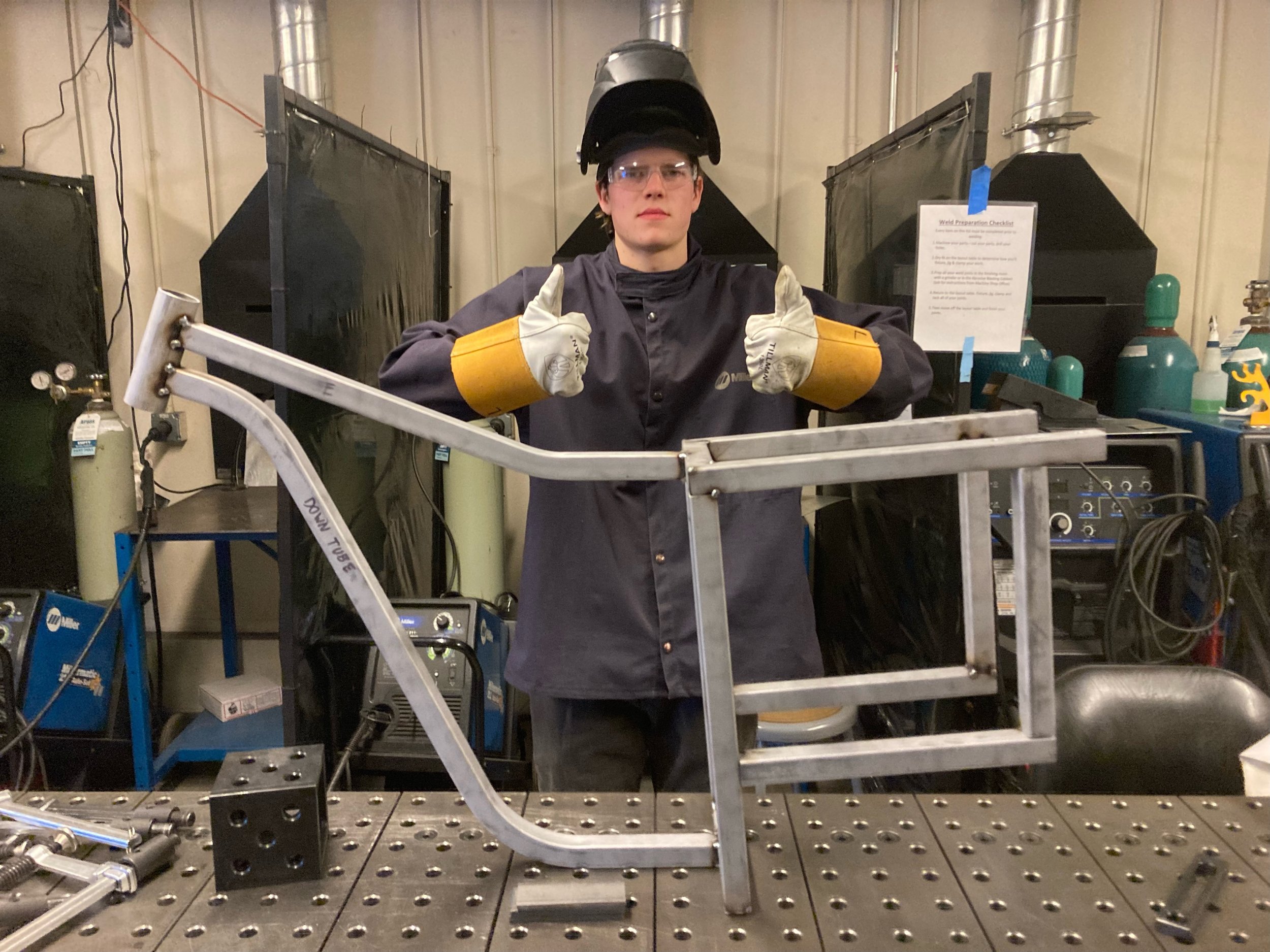
Cutting all bike frame components and welding them together
All individual components I worked on are displayed in the slide deck to the right.
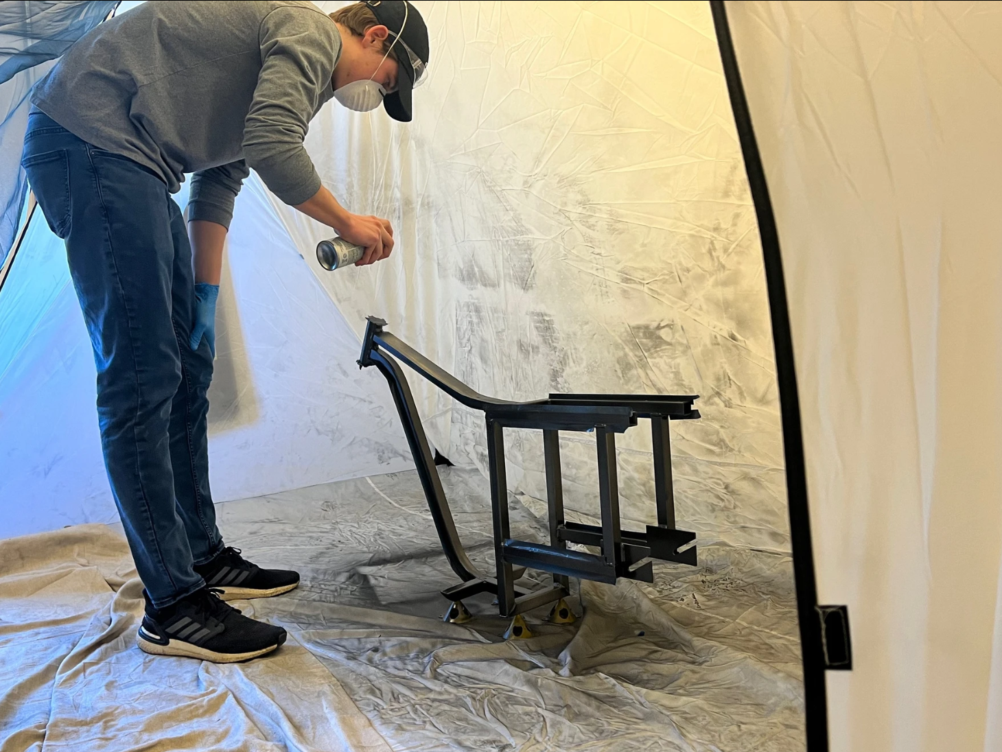
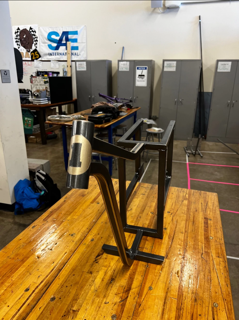
With all components machined and the framework welded, we proceeded to assemble the bike. Pictures of the completed bike are shown in the slide deck to the left.
Testing the Bike
Unfortunately, no videos were recorded during the competition. The only available footage is of our rider testing the bike, shown below:
Overall, we successfully manufactured a custom bike and secured 1st place in the endurance race, competing against eight other teams.
The most valuable lesson I learned was designing components for manufacturability. I also gained experience in performing failure analysis using FEA and verifying results through hand calculations. Additionally, I learned to operate knee mills and lathes to manufacture components with tight tolerances.
Key project highlights include:
The total cost of the bike was $172, staying under the $200 budget.
The final bike weight was 41 lb, below the 50 lb constraint.
The bike covered 24,200 ft (~4.5 miles) using the drill and rider momentum.
We not only won the endurance race but also set a record for the fastest time in the maneuverability race.
The throttle allowed for adjustable speed and power output.
The 2.4:1 gear ratio provided the necessary torque.


